A few days ago, I put together several simulations (find them in this post). However, I realized I had used the wrong relays in my simulation, or rather, I had bought the wrong ones in real life!
Because of that, I had to design a new circuit using the correct relays.
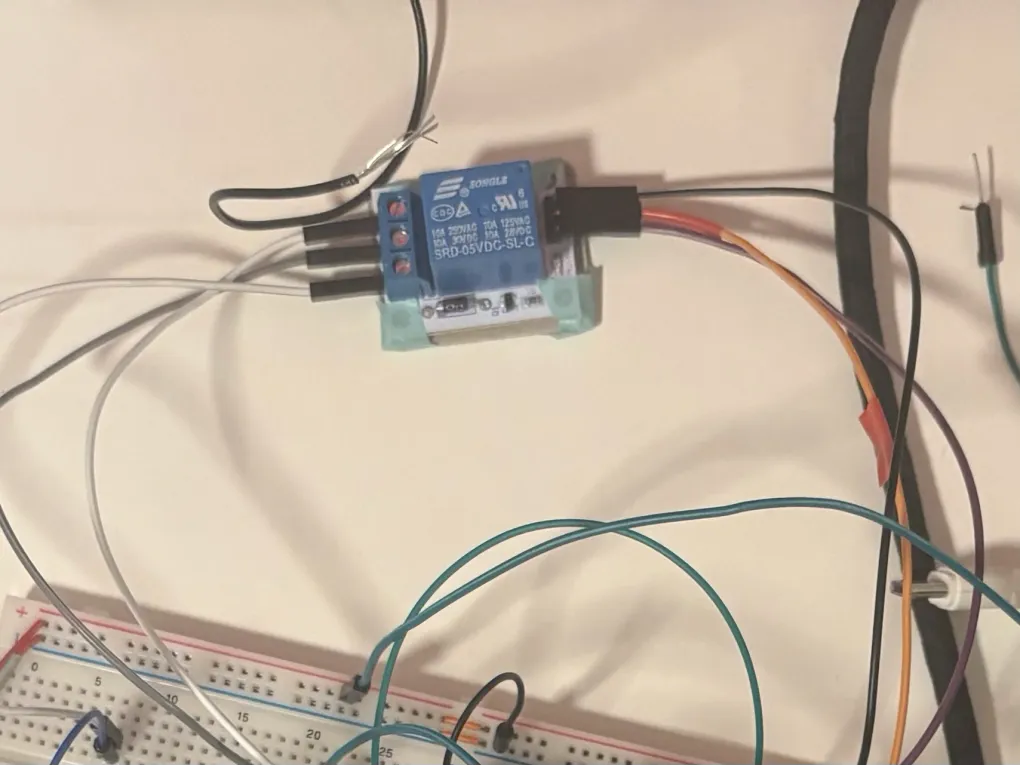
To verify that everything works, I added some LEDs. Since I’m using WPM406 relay modules, I don’t need to add external transistors or flyback diodes to my physical circuit; they are already built into the modules.
First test
For the first test, I wanted to confirm the relays were switching correctly. I used LEDs to represent the different states:
Talking Mode: If the relays are in their Normally Closed (NC) state, the red LED should light up when both phones are off-hook.
Music Mode: If the relays are triggered (Normally Open/NO state), one of the green LEDs should light up, depending on which phone is off-hook.
Second test
To see if the circuit actually performed under load, I tested it with sound.
Normally Closed: In talking mode, the intercom should be active so you can speak between the two phones. I tested this with some friends, and it worked perfectly!
Normally Open: In music mode, the Arduino plays audio from the micro SD card.
I initially tried to play two different songs at the same time, but the Arduino couldn’t handle it. Instead, I programmed it to play one song and switch the output between the two phones every 5 seconds. This allowed me to verify that both phones were receiving the audio signal correctly.
Arduino code ->