So, in the last two weeks, I built many circuits, wrote some code, and connected it to a Pi. This week I want to start coding everything, but… my wiring doesn’t work when everything is connected. To understand what I was doing and what is currently wrong, I decided to break my whole circuit into small parts.
Goal
I want to make an installation where two people can talk to each other using two old rotary phones. I don’t want to manipulate the internal circuit of the phones, so basically, I’m making a kind of telephone exchange. At some moments, an Arduino should infuse sound through one or both of the phones.
State 1: talking mode
Phones are just like an intercom
- Both phones are connected to each other.
- It should be possible to detect if one of the phones is on hook.
- If one of the phones is on hook, the circuit should change to state 2 (sound infusing mode).
State 2: sound infusing mode
Every phone can hear a different sound
- The phones are disconnected from each other.
- Each phone is connected to an Arduino.
- It should be possible to detect the on/off hook state of each phone.
- It should be possible to see what number is dialed on each phone.
Voice mail - recording If the other phone isn’t picked up, it should be possible to play and record a voicemail.
- It should be possible to record a sound.
State 3: Ringing
The phone rings when it is needed I also want one of the phones to ring when needed; this signal will be sent from the Arduino to the phone. But how? The bell works on AC current, while the Arduino and all the other components work on DC current. So connecting this in the wrong way will damage the Arduinos.
Technical specs
-
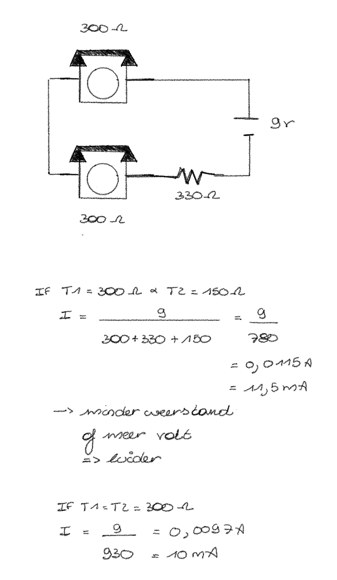
An old rotary phone works on a current of 20mA to 30mA.
-
The internal resistance of the phone is around 300 ohms or 0.3K ohms.
-
Peak voltages can occur during ringing, dialing a number, or when the phone changes from off/on hook.
-
I will use 3 Arduinos:
- 1 Pro Micro (5V): Used for all logic and detection.
- 2 Nano IoT (3.3V): Both used as Digital-to-Analog Converter (DAC) and Analog-to-Digital Converter (ADC).
Circuits
I made several circuits to test different things. I will list and explain them all.
Circuit 1: Intercom
With this circuit, you can have a conversation between Phone 1 and Phone 2.
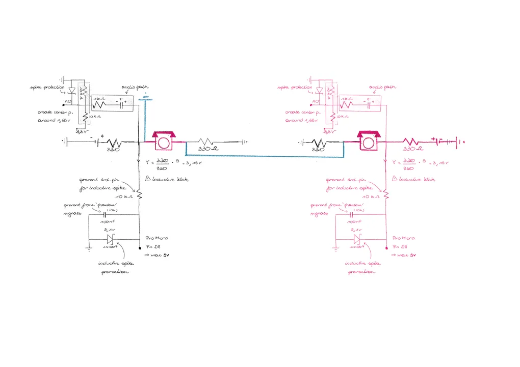
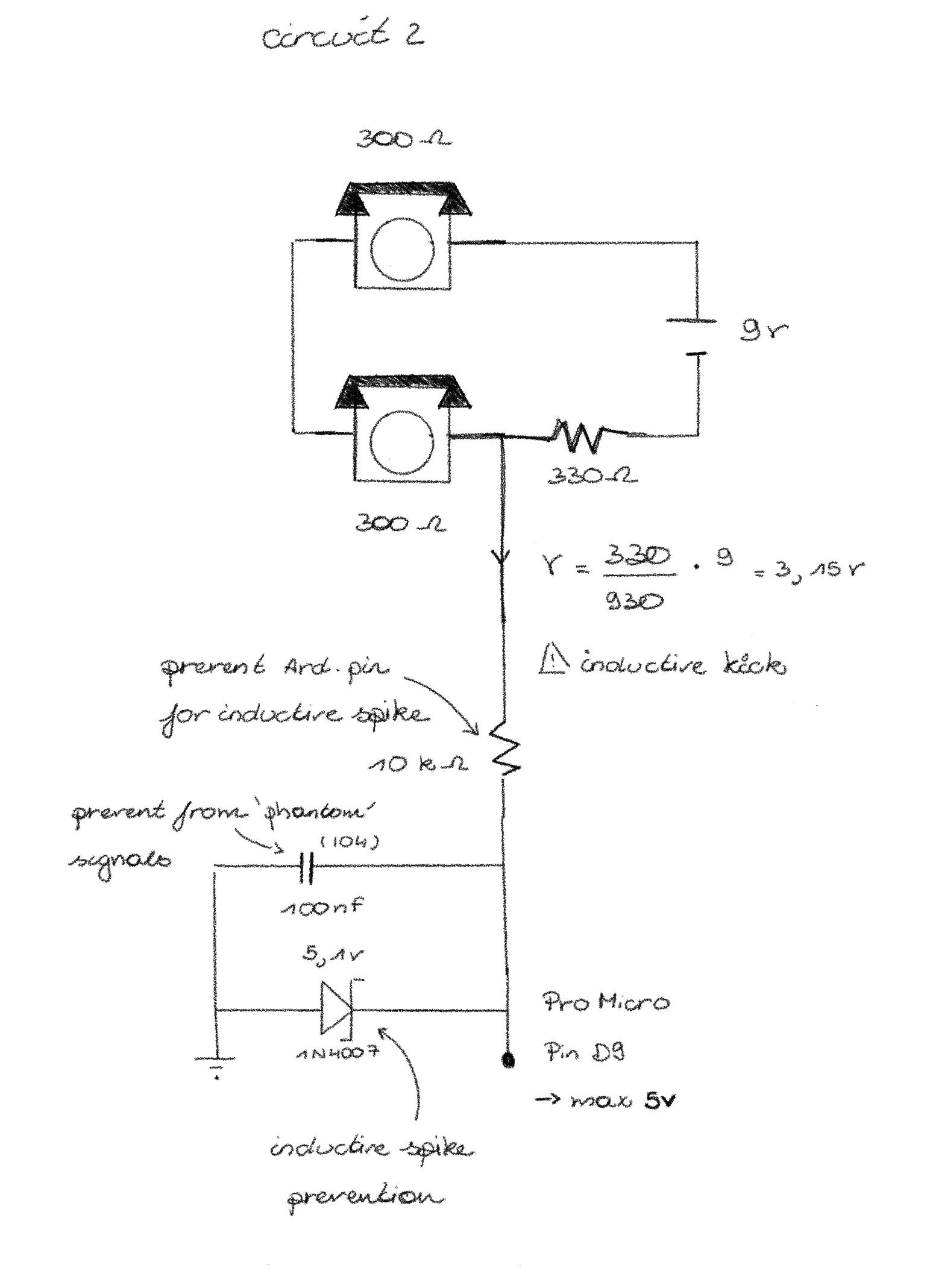
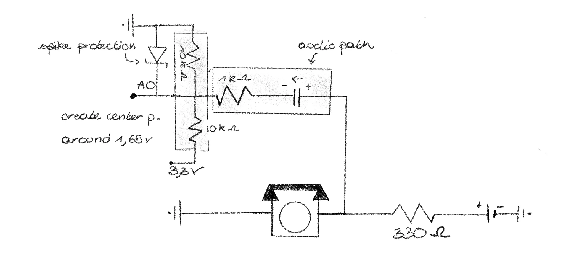
Circuit 2: Intercom, with on/off hook detection
With this circuit, you can have a conversation between Phone 1 and Phone 2. It also detects if one of the phones is on hook.
This detection is done by the Pro Micro (5V).
void setup() {
pinMode(9, INPUT);
Serial.begin(9600);
}
void loop() {
int val = analogRead(0);
if (val < 10) {
Serial.println("ON HOOK");
} else {
Serial.println("OFF HOOK");
}
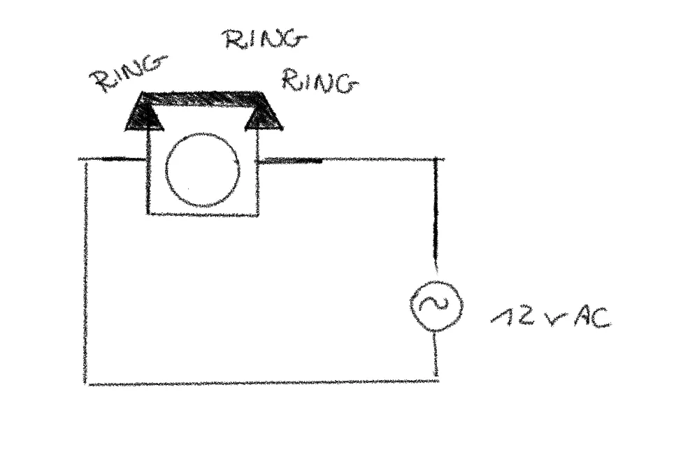
}Circuit 3: Separate phone, ring signal
This circuit lets one phone ring. To ring the phone, you need an AC signal. By using an AC current, the electromagnet switches polarity, which makes the hammer move and the bell ring.
Circuit 4: Separate phone, sound infusing with Arduino (and Pi)
With this circuit, you can play a sound through one phone. The sound is generated by the Arduino. But in the final product, the sound will be sent from a Pi to an Arduino Nano IoT (3.3V). This Arduino is used as a Digital-to-Analog converter. The Arduino then sends the signal to the phone.
void setup() {
pinMode(5, OUTPUT);
}
void loop() {
tone(5, 425); // Only test Phone 2
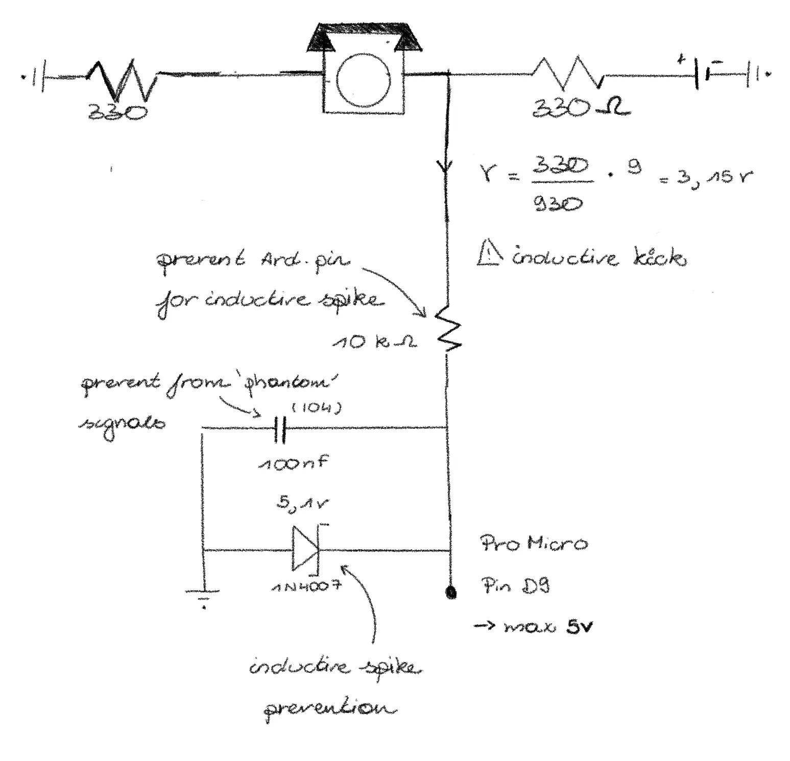
}Circuit 5: Separate phone, detect on/off hook and dialing a number
While dialing a number, you send high, short electrical pulses. If it is one short pulse, the user dialed a 1; if it is two short pulses, the user dialed a 2, and so on. If the phone is on hook, there will be no current flowing.
This detection is done by the Pro Micro (5V).
const int phonePin = A0;

// thresholds based on your measurement
const int ON_HOOK_LIMIT = 200;   // Near 0
const int OFF_HOOK_LEVEL = 780;  // Your measured Off-Hook
const int PULSE_THRESHOLD = 500; // The "midway" point to detect a break

int pulseCount = 0;
bool isOffHook = false;
bool inPulse = false;
unsigned long lastPulseTime = 0;
const int timeout = 400; // If no pulse for 400ms, dialing is done

void setup() {
  Serial.begin(9600);
  Serial.println("Ready. Lift handset to start.");
}

void loop() {
  int val = analogRead(phonePin);

  // 1. Hook State Detection
  if (val > (OFF_HOOK_LEVEL - 100)) {
    if (!isOffHook) {
      isOffHook = true;
      Serial.println("\n[OFF-HOOK]");
    }
  } else if (val < ON_HOOK_LIMIT) {
    if (isOffHook && pulseCount == 0) { // Only hang up if not currently dialing
      isOffHook = false;
      Serial.println("\n[ON-HOOK]");
    }
  }

  // 2. Pulse Detection (Only runs if handset is lifted)
  if (isOffHook) {
    // When dialing, the voltage drops from 780 towards 0 (the break)
    if (val < PULSE_THRESHOLD && !inPulse) {
      inPulse = true;
      pulseCount++;
      lastPulseTime = millis();
      Serial.print("."); // This is the dot you are seeing
    }
    // Return to "Off-Hook" level ends the pulse
    else if (val > PULSE_THRESHOLD && inPulse) {
      inPulse = false;
    }
  }

  // 3. Digit Finalizer (The fix for the "only dots" problem)
  if (pulseCount > 0 && (millis() - lastPulseTime > timeout)) {
    int digit = (pulseCount == 10) ? 0 : pulseCount;
    Serial.print(" Digit: ");
    Serial.println(digit);

    pulseCount = 0; // Reset for next digit
  }
}
From here on, I actually have no idea how to proceed… No idea how to connect the different circuits, nor how to record sound signals…
Circuit 6: Separate phone, record voicemail
To record a voicemail, you need to change the Analog signal to a Digital one.
This will be done by the Arduino Nano IoT (3.3V), used as an Analog-to-Digital converter.
Read everything about it here
Combined circuits
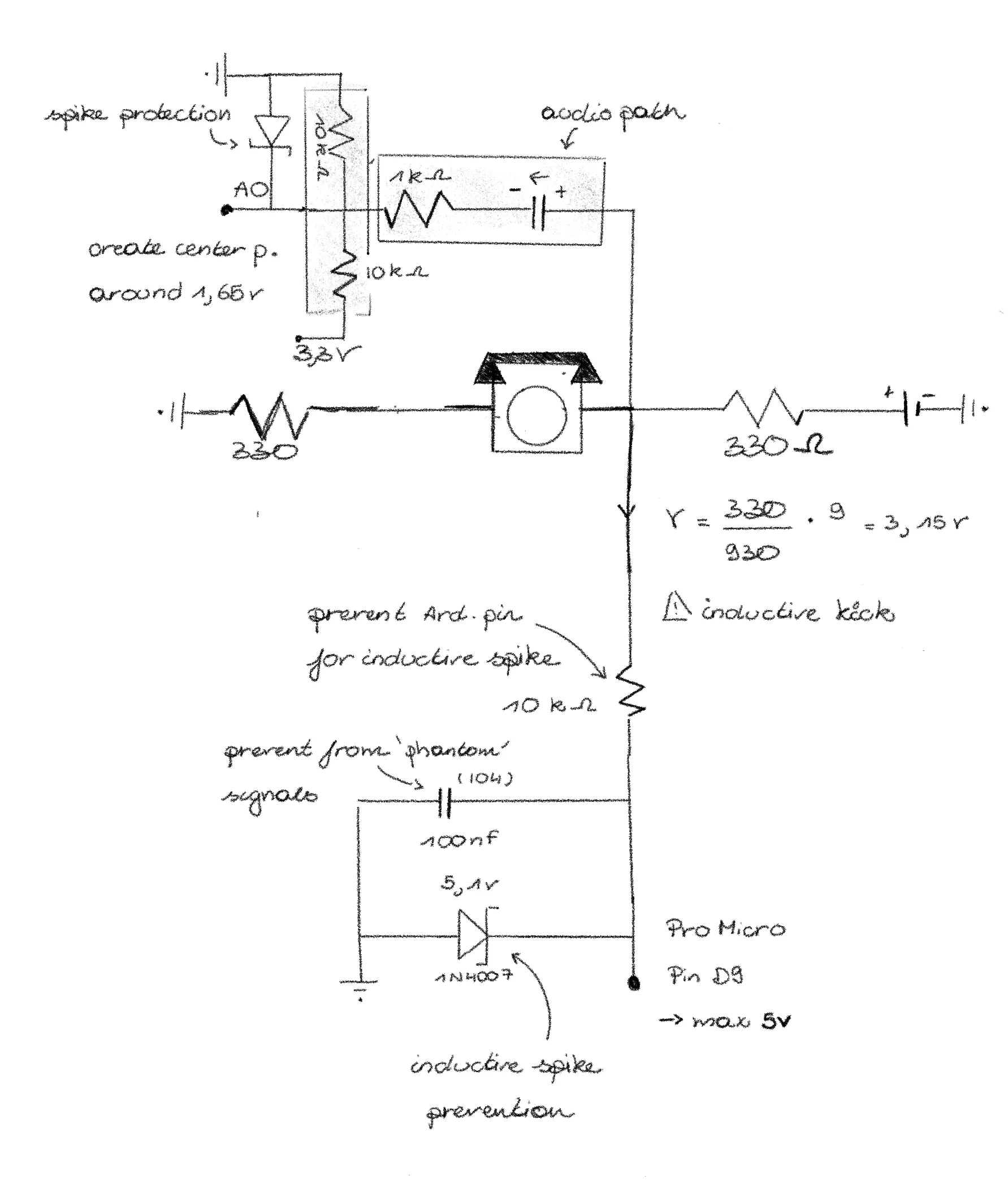
Circuit 7: Separate phone, sound infusing + on/off hook detection and dialing a number
Not tested in real life yet
To make the whole circuit for a separate phone, I combined the circuit for sound infusing with the circuit for on/off hook detection and dialing a number.
Circuit 8: Connection between separate phones and intercom
Not tested in real life yet To make it possible to switch between the separate phones and the intercom, I will need some relays to break the circuit at some points.
For now, I colored the common circuit pink, the extra wires for the intercom blue, and the extra wires for the separate phones black.
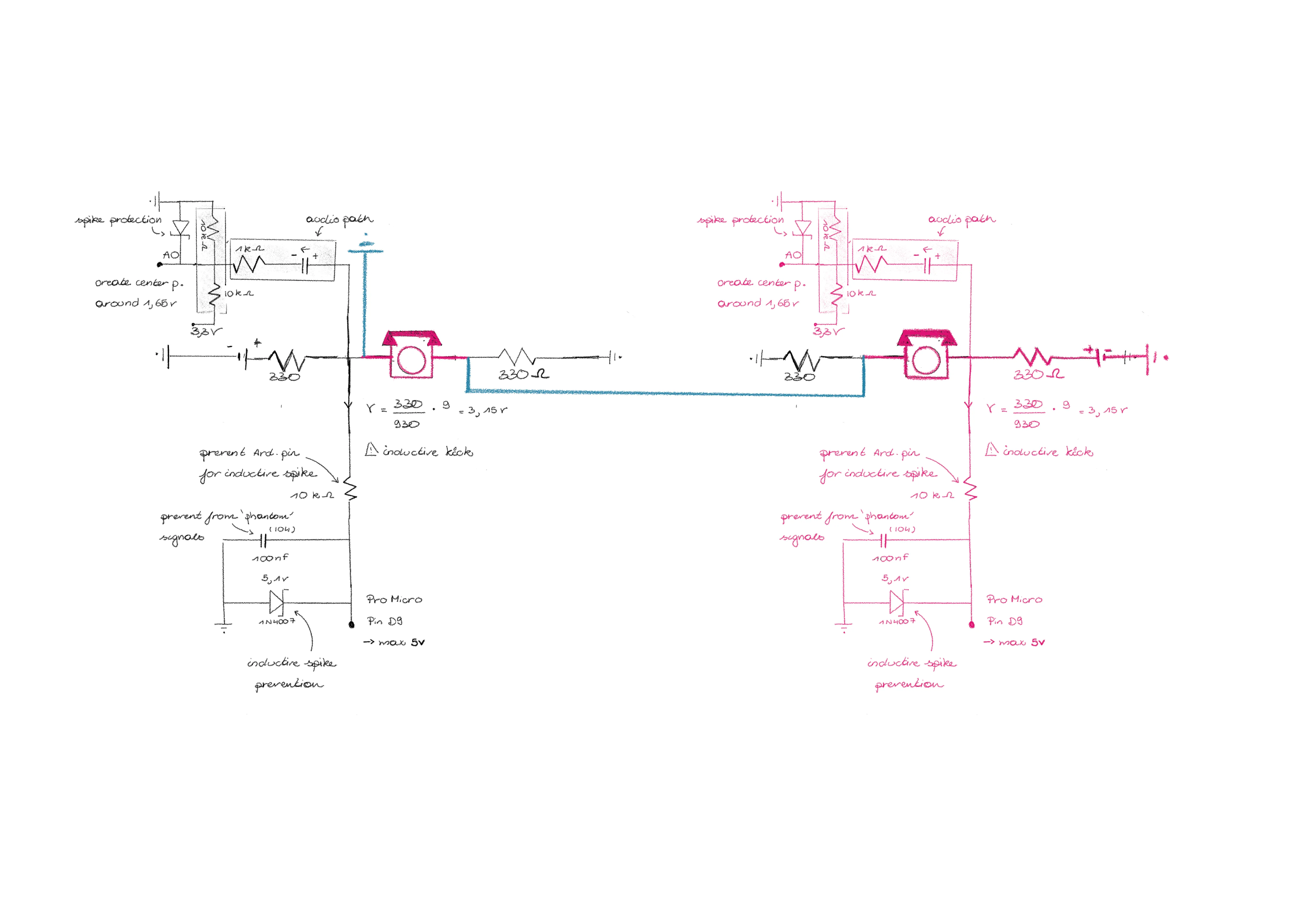
So by using relays, the circuit becomes something like this: ? At this moment, I usually don’t know how to connect them properly anymore. But in this post, I explain the final circuit.
Circuit 10: Separate phone + ring signal
Now, during ringing, the Arduino cannot detect if the phone is on hook or off hook. To make this still possible, the bell will ring in intervals.
Final circuit
Find the final circuit in the next post.