The breadboard is full. The wires are a mess. But most importantly: the whole circuit finally works.
With the prototype proven, it was time to make it permanent. I faced the classic maker’s dilemma: do I order a professional PCB, or do I build it myself?
The PCB Dilemma
Simon sent me a website where students can get discounts on custom-printed circuit boards. It’s a tempting shortcut, but looking into it made me realize that designing a board isn’t exactly that easy.
To do it right, I’d have to:
- Master KiCad (professional design software, currently I just draw everything in Figma 😅).
- Triple-check every trace to ensure no errors.
- Choose between dozens of finishes and thicknesses.
It felt like a project in itself. While I definitely want to learn KiCad in the future, I didn’t want to stall my progress now. So, I decided to go rogue and build the board myself on a tripod protoboard.
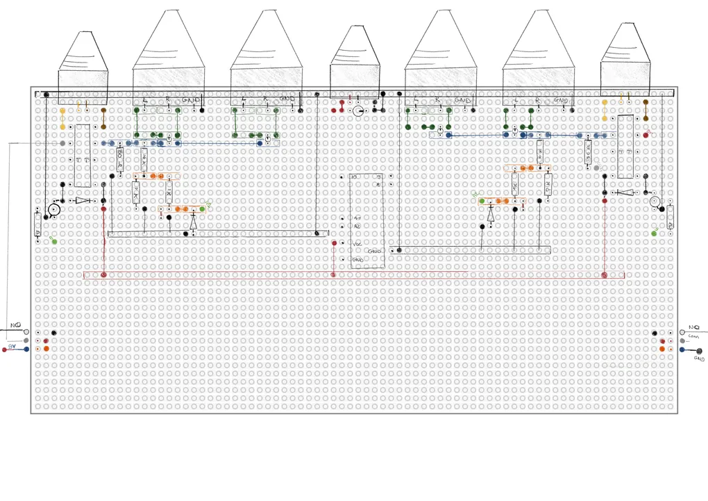
Step 1: drawing
I looked for software to help me map out the components, but everything felt too “heavy.” In the end, I went back to basics: pen and paper.
I spent way more time than I expected sketching out where every resistor, relay, and transistor should sit to keep the traces as clean as possible. It’s like a puzzle where the pieces are connected by copper. By the time I finished, I had what I thought was a perfect soldering plan.
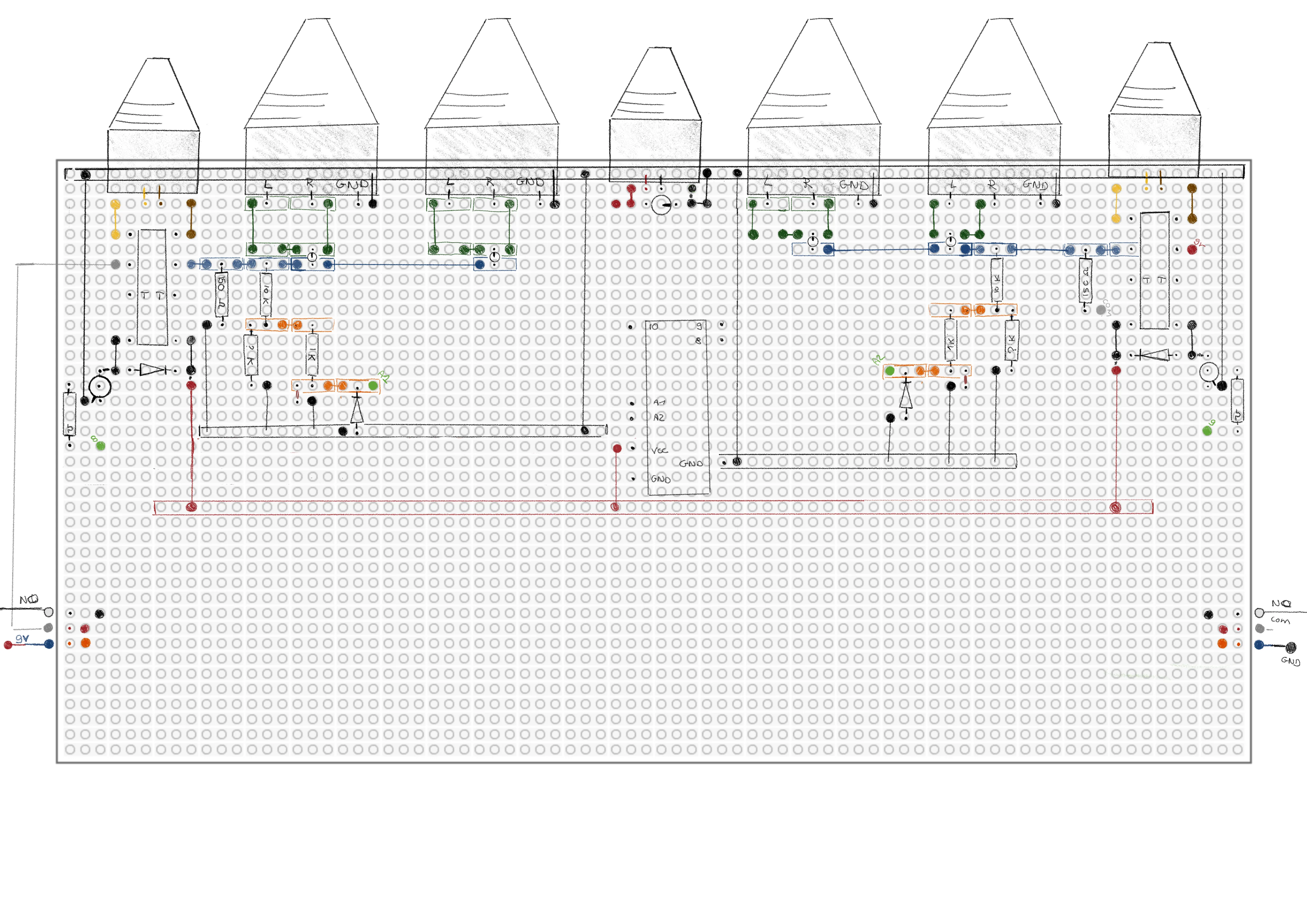
(Spoiler alert: my connections could be prettier, but for a first-timer, I was proud.)
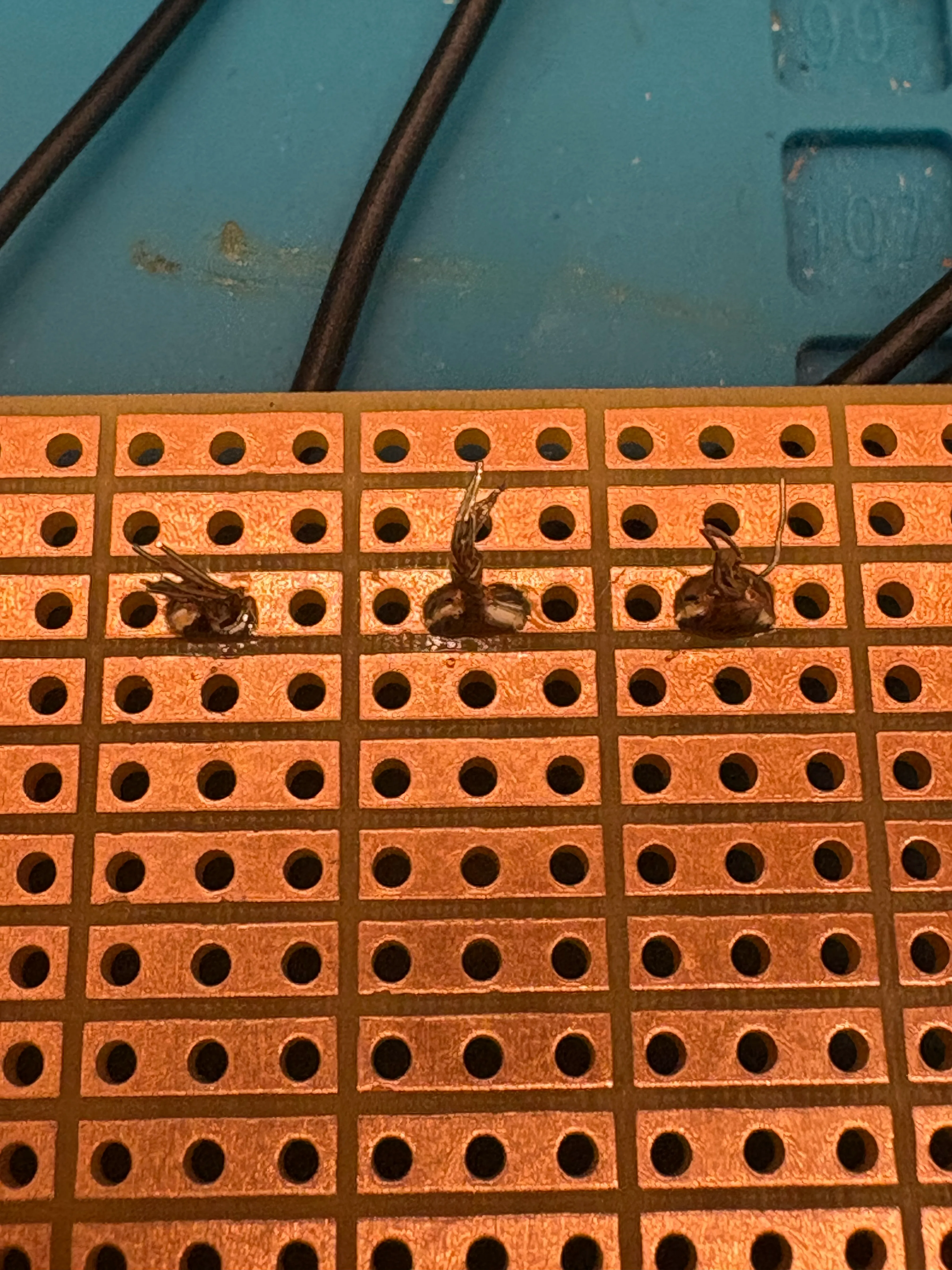
Step 2: soldering
Then came the actual soldering. To be honest, the first few joints were a disaster. I haven’t touched a soldering iron in over 10 years.
A huge thank you to Ashley for stepping in and teaching me the basics of soldering. After all that, I finally had a board with every connection in place.
I had a permanent circuit. I had a finished board… or so I thought.
Read the rest of my soldering adventure in Part 2!